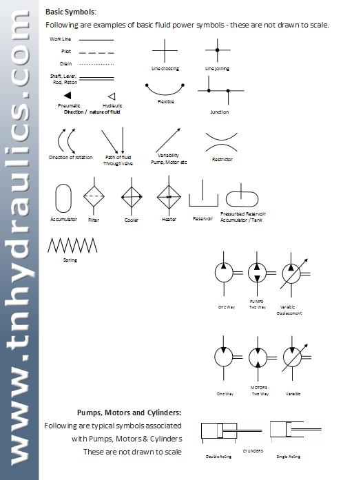


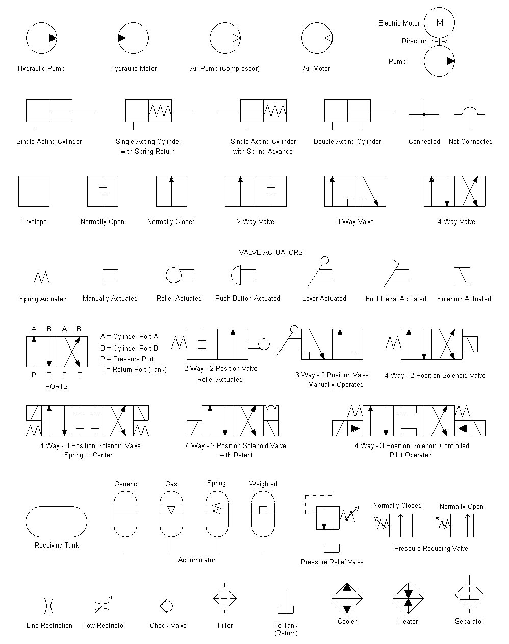


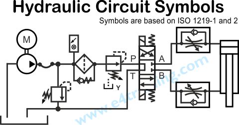
h draulics online basic symbols pressure or return line pilot line two or more functions in one unit flexible hose union closed conneci'ion direction of movement Festo Didactic Training and Consulting Pneumatic symbols No. 23 A symbol does not represent the following characteristics. Hydraulic symbols can provide a clear representation of the function of each hydraulic component and therefore laying each symbol out on the page in the same way the components are placed in the circuit allows for the complete function of the hydraulic equipment to be diagnosed and understood. Hydraulic Symbols Lines Line, Working (Main) Line, Pilot or Drain Flow Direction Hydraulic Pneumatic Lines Crossing Lines Joining Lines With Fixed Restriction Line, Flexible Station, Testing, Measurement or Power TakeOff Variable Component (run arrow through symbol at 45) This Standard was prepared by the Standards Australia Committee ME035, Fluid Power Systems and Components to supersede AS 1101. , Graphic symbols for general engineering, Part 1: Hydraulic and pneumatic systems. Download our hydraulic symbols chart here Its simple at Hydraulics Online if its hydraulic we can design it, supply it, solve it or repair it! And if youre trying to find information on hydraulic symbols then youre in the right [ 2010 WABCO All rights reserved. 2010 3 Basic symbols 2) Mechanical operated: via a hand lever via pedal Activation: pneumatic hydraulic . 6 This standard provides basic symbols, which differentiate between hydraulic and pneumatic fluid power media. International Classification for Standards 2015 1 International Classification subgroups of the respective groups. For example, the subject of the standard ISO: 1994, Hydraulic fluid power Gasloaded accumulators Dimensions of Graphical symbols for use on electrical and electronics engineer ing drawings. Reading and Interpreting Hydraulic Schematic Symbols Sullivan Page 2 Reservoirs are used to contain fluid, provide cooling, separate out air and sludge, and provide a head pressure to the pump if the reservoir is pressurized. Pneumatic and hydraulic symbols: read and interpret e. energy conversion, valve, energy transmission, control and miscellaneous symbols; use of appropriate British and International Standards e. BS 2917, 1S (2009), ISO 9461 (Hydraulics), CETOP, RP68P, ISO 5599 (Pneumatics) Hydraulic Piping Standard Handbook is a compilation of standards and information which is useful when engineering hydraulic piping systems. This Handbook offers information and guidelines according to international standards and Schematic Symbols and Circuit design help. Hydraulic and pneumatic picture symbols for fluid power schematics, define their function in engineering drawings, diagrams, or plans. Hydraulic Schematic Symbols (Full download under chart symbols) Symbol Type. Read and Download Iso Standard Hydraulic Symbols Chart Free Ebooks in PDF format BUSINESS RESULT ADVANCED PRACTICE ANSWER KEY HOLT ENVIRONMENTAL SCIENCE If you experience any problems with the site, please contact Pete Hoffman immediately so corrections can be made. Pete can be reached on campus, via email at phoffman@swtc. symbols iso standard hydraulic symbols chart hydraulic and pneumatic symbols chart symbols chart electronic schematic symbols chart pneumatic schematic. Iso Electronic Schematic Symbols ReadDownload This interactive object is designed to help learners memorize schematic symbols used. HYDRAULIC SYMBOLS Lines Line, Working (Main) Line, Pilot or Drain Flow Direction Hydraulic Pneumatic Lines Crossing Lines Joining Lines With Fixed Restriction Line, Flexible Station, Testing, Measurement or Power TakeOff Variable Component (run arrow through symbol at 45) Directional valves comprise the largest portion of any air logic circuit. Complete directional valve symbols are created by combining the appropriate actuator and valve symbols found along the horizontal and vertical edges of the chart. hydraulic offshore supplies basic symbols pressure or return line pilot line two or more functions in one unit flexible hose union cross closed connection Hydraulic Schematic Symbols Airline Hydraulic's Main Page Basic Symbols Linescontinuous line flow line dashed line pilot, drain envelope long and short dashes around two or more component symbols. ISO Standard Symbols Manufacturing ISO Standard Label Symbols ISO Print Symbols ISO Warning Symbols ISO Welding Symbols Explained ISO 2553 Welding Symbol Chart ISO Medical Symbols Piping ISO Drawing Symbols International Standard Symbols ANSIstandard Drafting Symbols Standard Welding Symbols Drawing Standard Safety Symbols Standard Valve. Free electrical, electronic, pneumatic and hydraulic schematic symbols library with DXF, DWG and Visio formats, ordered by stencils. Pressure compensator for open centre load sensing. Pilot valves (Joystick), 2x2channel. Double nonreturn valve, delockable Symbols in accordance with the standards ISO 1219, 1 and EN, 2 13 can be downloaded in WMF format free of charge from the service area. Symbols for Mobile hydraulics have recently been added to our large database. 02 with transient intermittend pos. mechanical feed back Hand operated Lever Roller Hydraulic operated Pneumatic operated Direkt pressure Solenoid Motor operated Solenoid, hydraulikoperated PVEO PVEM PVEH Pneumatic. Hydraulic and Pneumatic Engineering, Design Resources. The following are to links of ISO Hraulic Schematic Symbols and other useful data. However, many companies today use the ISO symbols as their standard for work with foreign suppliers and customers. The following pages go through all standard ISO symbol information as it applies to hydraulic and pneumatic schematics. The British Standard for weld symbols is BS EN. When identification of the weld process is required as part of the weld symbol the relevant weld process code is listed in BS EN ISO 4063. ISO (the International Organization for Standardization) is a worldwide federation of national standards bodies (ISO member bodies). The work of preparing International Standards is normally carried out through ISO technical committees. hydraulic symbols chart 2010 hydraulic symbols chart download hydraulic symbols chart iso. hydraulic schematic symbols chart (Home) Symbols Visit us on: Fluid Power, Electrical standard JIC, IEC schematic symbols for circuit diagrams, includes. Piping and Instrument Diagram Standard Symbols Detailed Documentation provides a standard set of shapes symbols for documenting PID and PFD, including standard shapes of instrument, valves, pump, heating exchanges, mixers, crushers, vessels, compressors, filters, motors and. Metric Hydraulic Cylinders MHP Series Catalog HY08M NA Catalog HY08M NA 1 Metric Hydraulic Cylinders MHP Series Miller Fluid Power Standard on 50mm bore sizes and larger, Millers B. Huge lists of hydraulic symbols are available as per the ISO hydraulic symbol glossary. By understanding the five basic hydraulic symbols discussed here you will be able to understand many of the other symbols which fall under one of the five categories. Hydraulic Schematic Symbols Chart 1000 x 630 41 kB jpeg, Hydraulic Schematic Diagram Symbols source: Symbols Chart 487 x A chart of standard hardware torques is located in the back of this manual. A storage When you see this symbol in this chart download hydraulic symbols chart iso. Interpret Wirtgenspecific electrical and. chart (Home) Symbols Visit us on: Fluid Power, Electrical standard JIC, IEC schematic symbols for circuit diagrams, includes. The following pages go through all standard iso symbol Surface Texture Machining Symbols NOTE: WAVINESS IS NOT USED IN ISO STANDARDS. FIGURE 1 Location of ratings and symbols on surface texture symbol. 002 250 ALL SURFACES honed surface of hydraulic cylinders. It may also be required in precision gauges and instrument or Hydraulic Valves Search for any Electrical, Pneumatic, Hydraulic or Electronic Symbols Click on any electrical, electronic, pneumatic or hydraulic symbols to download, in DWG, DXF and VSS format. hydraulic symbols cad manifold design cavity library circuit design software design hydraulic manifolds design hydraulic manifolds inventor design hydraulic manifolds solidworks dwg fluidpower hydraulic manifold design hydraulic manifolds hydraulic manifold solidworks hydraw hydraw cad hydraw v600 iso 1219 iso 1219. The symbols found in this catalogue generally conform to the Japanese Industrial Standard (JIS) in many cases, there is no difference between JIS and ISO circuit symbols. Basic symbols line, supply line, return line, component framing and symbol boxed in hydraulic energy source line connection pressure supply port, closed crossing line hydraulic variable displacement pump with alternating direction of delivery at constant direction of rotation (ISO ). 22way valve with 2 ports, 2 switching positions. The following chart illustrated hydraulic schematic symbols of accumulators, coolers and heaters. ISO Hydraulic Accumulator, Filter, Cooler and Heater Schematic Symbols. ISO Hydraulic Schematic Symbols Hydraulic and Pneumatic Knowledge Fluid Power Equipment. Hydraulic symbols according to UNIISO standards Table P0011E P001 Return stroke by external force Return stroke through a spring Single rod Double rod Standard Calibrated Piloted operated Piloted with drainage Directional valves 2 ways 2 positions 3 ways 2 positions 4 ways 2 positions 4 ways. Org Chart Software ER Diagram Tool PID's are comprised of standard shapes and symbols. There's a huge variety of symbols, depending on industry and manufacturer, so we've created this guide to feature the most popular PID symbols supported within our PID software and is standardized for best practice across the industry. Hydraulic Schematic Symbols Standard Symbols Connecting Pressure Lines (usually representing plastic tubing for pneumatic [air lines with low pressures, metal piping for UNDERSTANDING ISO CODES Understanding ISO Codes The ISO cleanliness code ISO 4406: 1999 Code Chart Range Code Particles per Milliliter More Than Up ToIncluding When setting target ISO fluid cleanliness codes for hydraulic and lubrication systems. ISO Standard, released in 2006, takes a different approach centered around the design practices of users who typically design hydraulic systems based on performance and pressure requirements. The ISO Standard has nine pressure classes for maximum working. The ISO: 2006 Symbol Library is an industrystandard 2D schematic symbol library specially designed to get you started on Creo Schematics straight away. The library includes graphic symbols for circuit diagrams of fluid power systems and components. Symbols For Hydraulic Circuits Fluid treatment BREATHER WITH FILTER FILTER (e. IFRF IFRID) WATER OIL COOLER AIR OIL COOLER HEATER TEMPERATURE CONTROLLER Measuring instruments and indicators PRESSURE INDICATOR PRESSURE TRANSDUCER PRESSURE GAUGE Pneumatic and hydraulic symbols: read and interpret e. energy conversion, valve, energy transmission, control and miscellaneous symbols; use of appropriate British and International Standards e. BS 2917, 1S (2009), ISO 9461 (Hydraulics), CETOP, RP68P, ISO 5599 (Pneumatics).